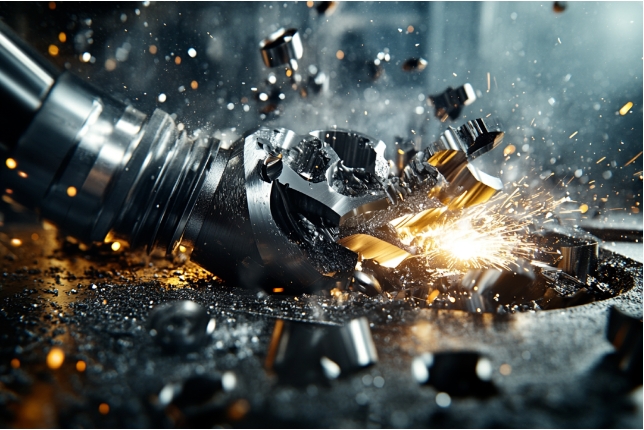
Tool wear is a serious problem in the machining process. It not only affects the machining accuracy of the product, but also greatly increases the production cost. To effectively solve the problem of tool wear, it is necessary to master some basic theoretical knowledge, including cutting principles, material properties and tool geometry parameters. Based on this knowledge, we have sorted out 7 principles to help optimize tool use and extend tool life.
Tool wear is a serious problem in the machining process. It not only affects the machining accuracy of the product, but also greatly increases the production cost. To effectively solve the problem of tool wear, it is necessary to master some basic theoretical knowledge, including cutting principles, material properties and tool geometry parameters. Based on this knowledge, we have sorted out 7 principles to help optimize tool use and extend tool life.

Choose the right tool according to the material
When the cutting edge of the tool becomes blunt, it will cause uneven cutting, leaving irregular lines and burrs on the surface of the workpiece, resulting in increased surface roughness. It is very important to choose the right tool according to the material, and comprehensive consideration should be given to the processing material, processing requirements, tool durability and economy. Here, we directly give the 10 materials that need the most attention, which are very likely to cause tool wear:
① High-hardness steel (such as hardened steel, mold steel): The material has high hardness, which is easy to cause rapid wear or chipping of the tool. It is usually recommended to use coated carbide tools or PCBN (poly cubic boron nitride) tools. Coated carbide tools have excellent wear resistance, while PCBN tools show excellent wear resistance in the processing of extremely high hardness materials.
② Stainless steel (such as 304, 316): Stainless steel has strong viscosity and poor thermal conductivity, which is easy to form built-up edge, resulting in accelerated tool wear. It is usually recommended to use carbide tools with TiAlN coating or AlCrN coating. These coatings can effectively reduce the formation of built-up edge and improve the wear resistance of the tool.
③ Heat-resistant alloys (such as Inconel, Hastelloy): These materials generate high temperatures during processing, and the tools are prone to thermal wear. It is recommended to use ceramic tools or PCBN tools. Ceramic tools have extremely high heat resistance, while PCBN tools show good wear resistance in high-temperature cutting environments.
④ High-silicon aluminum alloy: The material contains hard silicon particles and is highly abrasive, which easily causes rapid tool wear. It is recommended to use uncoated super-hard carbide tools or diamond-coated tools. These tools have extremely strong wear resistance and are suitable for processing highly abrasive materials.
⑤ Cast iron (such as gray cast iron, ductile iron): The graphite content in cast iron can easily cause tool wear, especially during rough machining. Uncoated carbide tools or ceramic tools are usually used, which show excellent wear resistance in the machining of high-hardness materials.
⑥ Titanium alloy: Due to the low thermal conductivity and high chemical activity of titanium alloy, the tool is prone to sticking and wear. It is recommended to use coated carbide tools, such as AlTiN coating, which have excellent wear resistance in high temperature environments and can reduce adhesion.
⑦ High manganese steel: This type of material has a strong tendency to work hardening, and the tool is prone to wear during machining. It is recommended to use coated carbide tools or ceramic tools, especially carbide tools with high hardness coatings, which can effectively deal with the wear problem caused by work hardening.
⑧ Composite materials (such as carbon fiber composite materials): The hard fibers and resin matrix in the composite materials cause severe wear on the tool. It is recommended to use diamond-coated tools or PCD (polycrystalline diamond) tools, which have extremely high wear resistance and are suitable for machining high-hardness and high-abrasive composite materials.
⑨ High nickel alloy: The cutting force is large and hard spots are easily generated, resulting in severe tool wear. It is recommended to use coated carbide tools or ceramic tools. Ceramic tools can maintain sharp cutting edges at high temperatures and reduce wear.
⑩ Sintered hard materials (such as ceramic materials): These materials will cause severe abrasive wear to the tool during processing. Usually, super-hard coated carbide tools or PCD tools are used. These tools have extremely strong wear resistance and high temperature performance, which can effectively extend the tool
Correctly set cutting parameters
Inappropriate cutting speed, feed rate and cutting depth may cause tool wear. When the cutting speed is too high, the friction between the tool and the workpiece increases, which is easy to generate a lot of heat and aggravate the thermal wear of the tool. Excessive feed rate will cause a sharp increase in cutting force, and the tool will be subjected to greater impact force, which may cause edge fracture or accelerated wear. Excessive cutting depth will increase the load on the tool, causing the cutting edge to bear uneven force, and ultimately cause rapid edge wear or even damage. Considering the following factors, it is not difficult to analyze what parameters are more suitable.
(1) Material properties
① Hardness: The higher the hardness, the lower the cutting speed is usually required to reduce tool wear. In addition, when processing high-hardness materials, a smaller cutting depth and moderate feed rate should be selected to avoid excessive cutting force causing tool fracture or workpiece deformation.
② Toughness: Materials with high toughness are prone to deformation during processing, which means that the feed rate needs to be appropriately reduced to reduce cutting force fluctuations, while the cutting speed needs to be slightly increased to achieve a smoother cutting process and avoid the impact of material rebound on surface quality.
③ Thermal conductivity: When the thermal conductivity of the material is poor (such as stainless steel and titanium alloy), it is difficult to dissipate heat during cutting, which can easily lead to excessive temperature in the cutting area. At this time, the cutting speed should be reduced and the cutting depth should be increased to ensure that the heat is effectively removed. At the same time, the feed rate should be properly controlled to avoid heat accumulation causing workpiece deformation or surface quality degradation.
④ Viscosity: Materials with strong viscosity (such as stainless steel and aluminum alloy) are easy to adhere to the tool, forming built-up edge, which affects the processing quality. In order to alleviate this phenomenon, it is recommended to increase the cutting speed and reduce the feed rate at the same time, so that the cutting process is smoother and adhesion and built-up edge formation are reduced.
⑤ Work hardening: Materials that are prone to work hardening (such as high manganese steel) will rapidly increase in hardness during cutting, making subsequent cutting more difficult. Lower cutting speeds and smaller feed rates should be used to reduce the impact of work hardening, while keeping shallow cutting to avoid too thick a hardened layer.
(2) Tool characteristics
① Hardness: The harder the tool, the higher the cutting speed and smaller the cutting depth can usually be set to make full use of its wear resistance. However, it should be noted that excessive hardness may reduce the toughness of the tool, so excessive feed should be avoided during processing to reduce the risk of tool chipping.
② Toughness: Tools with better toughness usually allow larger feeds and cutting depths, and are particularly suitable for intermittent cutting or processing workpieces with irregular surfaces. Tools with high toughness can withstand greater impact forces, so larger cutting parameters are often used in rough processing.
③ Wear resistance: Tools with high wear resistance remain sharp during long-term cutting, so the cutting speed can be increased accordingly, and the feed rate can be increased moderately to improve production efficiency. However, when processing materials with extremely high hardness, the cutting depth still needs to be controlled to avoid aggravating wear.
④ Heat resistance: Tools with strong heat resistance allow the use of higher cutting speeds, especially in high-temperature cutting environments, and their performance is stable and not easy to soften. It is suitable for increasing cutting parameters in the cutting of high-temperature alloys or difficult-to-process materials to achieve efficient processing.
⑤ Chemical stability: Tools with good chemical stability can maintain the integrity of the cutting edge during cutting, and are suitable for processing materials that are prone to chemical reactions. When setting cutting parameters for this type of tool, the feed rate and cutting speed can usually be increased moderately without affecting the tool life.
(3) Processing method
① Roughing: During roughing, due to the large cutting force, the tool wear is more serious. In order to slow down the tool wear, it is recommended to reduce the cutting speed while maintaining a moderate feed rate. Although the cutting depth is large, it is necessary to avoid exceeding the tool load limit to ensure the durability of the tool.
② Finishing: The cutting depth and feed rate in finishing are small, but the cutting speed is usually high. In order to prevent the tool from accelerating wear due to friction heat at high speed, the cutting speed can be moderately reduced. Especially when processing sticky materials (such as stainless steel), the cutting speed should be set more carefully to prevent built-up edge.
③ Intermittent cutting: Intermittent cutting has a large impact on the tool and is prone to wear and chipping. In order to prevent this wear, the cutting speed and feed rate should be significantly reduced to ensure the smoothness of each cut-in and cut-out, thereby reducing the impact wear of the tool.
④ Continuous cutting: In continuous cutting, due to the continuous contact between the tool and the workpiece, heat accumulation is likely to occur, leading to thermal wear. In order to prevent the tool from overheating and wear, the cutting speed can be appropriately reduced, and the effective use of coolant can be ensured to reduce the temperature of the cutting area.
⑤ Heavy cutting: During heavy cutting, the cutting force on the tool is extremely large, and the wear is aggravated. In order to reduce wear, it is recommended to control the cutting depth, reduce the feed rate, try to avoid excessive cutting load at a single time, and maintain the stability of the tool edge.
⑥ High-speed cutting: High-speed cutting is prone to extremely high cutting temperatures, resulting in thermal wear of the tool. In order to reduce wear, the cutting time can be shortened and the cooling effect can be increased. At the same time, the feed rate can be strictly controlled to avoid excessive cutting loads that affect the tool life.
(4) Machine tool rigidity
① Structural rigidity: High-rigidity machine tools allow higher cutting speeds and larger feed rates. For example, the cutting speed can be increased to more than 300 m/min, and the feed rate can be increased to more than 0.3 mm/rev. For machine tools with insufficient rigidity, the cutting speed (such as 150-200 m/min) and feed rate need to be reduced to avoid vibration causing tool wear.
② Spindle rigidity: When the spindle rigidity is high, a higher cutting speed (such as 400-800 m/min) and a larger cutting depth (such as more than 5 mm) can be used to improve the processing efficiency. If the spindle rigidity is low, the cutting depth (such as less than 2 mm) and feed rate (such as less than 0.1 mm/rev) need to be reduced to avoid spindle runout and vibration affecting the processing accuracy.
③ Stability of fixture and workpiece clamping: When the fixture stability is high, a larger cutting depth (such as 4-8 mm) and a higher feed rate (such as 0.3 mm/rev) can be used to improve the cutting efficiency. If the clamping is unstable, the cutting depth (such as 1-3 mm) and feed rate need to be reduced, and the cutting speed should be appropriately reduced to ensure that the workpiece does not shift or vibrate.
④ Guideway rigidity: When the guideway rigidity is high, the machine tool can still maintain a high cutting speed (such as more than 500 m/min) and a large feed rate (such as 0.4 mm/rev) when moving at high speed, thereby improving the processing efficiency and surface quality. When the guide rail rigidity is insufficient, the cutting speed and feed rate should be appropriately reduced to reduce vibration and tool wear.
⑤ Machine tool foundation rigidity: High foundation rigidity allows the machine tool to remain stable under large cutting forces, allowing higher cutting parameters. If the foundation rigidity is insufficient, the cutting speed and feed rate need to be greatly reduced (such as 150-200 m/min, 0.1 mm/rev or less) to avoid vibration affecting the processing effect.

During the vibration or chattering process, vibration or chattering is one of the key factors causing tool wear. Vibration not only increases the cutting force, but also aggravates the heat accumulation in the cutting area, causing the tool to quickly passivate at high temperatures. At the same time, vibration will cause ripples or tool marks on the workpiece surface, affecting the final surface roughness and dimensional accuracy. To avoid vibration or chattering, in addition to the correct setting of cutting parameters as mentioned above, the following points are worth noting:
(1) Tool geometry
① Optimization of rake angle and back angle: Increasing the rake angle can reduce the cutting force and thus reduce the occurrence of vibration, but it should be noted that when cutting high-hardness materials, too large a rake angle may lead to insufficient tool rigidity, and it needs to be adjusted according to the specific material properties.
② Adjustment of the main rake angle: Selecting a suitable main rake angle can effectively disperse the cutting force and reduce vibration. Too large a main rake angle will lead to excessive radial force and increase the risk of deformation of the workpiece, while too small a main rake angle may cause increased vibration.
③ Edge passivation: Micro-passivation of the edge (such as R0.1-R0.2) can increase the wear resistance and impact resistance of the cutting edge, thereby reducing the chipping caused by vibration, especially when processing sticky materials, it can reduce the generation of built-up edge.
④ Cutting edge shape optimization: The use of cutting edges with special shapes (such as wavy or micro-toothed) can disperse the cutting force and reduce vibration, which is suitable for improving surface quality in fine processing.
(2) Vibration-damping tools
① Built-in damping structure: Some tools are designed with built-in damping materials or vibration-damping devices, which can effectively absorb vibration energy during high-speed cutting and are suitable for processing long cantilevers or slender workpieces.
② Tool material selection: In a processing environment with large vibration, the selection of carbide tools or coated tools with high impact resistance can reduce wear. Although ceramic tools have good wear resistance, they are prone to chipping in a vibrating environment and need to be selected with caution.
③ Adjustable vibration-damping tools: Some tools are designed with adjustable vibration-damping mechanisms. The vibration frequency is changed by adjusting the internal counterweight of the tool to avoid the resonance zone.
④ Multi-layer coating technology: Multi-layer coating not only increases the wear resistance of the tool, but also slows down the transmission of vibration, which is suitable for the vibration resistance requirements during high-speed cutting.
(3) Clamping stability
① Reasonable selection of fixtures: Selecting fixtures with high rigidity and multi-point support can significantly improve the stability of the workpiece and reduce the displacement during the cutting process. It is suitable for processing thin-walled parts or irregular workpieces.
② Uniformity of workpiece clamping: Ensure that the workpiece is evenly stressed in the fixture to avoid deformation or vibration caused by excessive local clamping force. Especially in the processing of long-axis workpieces, stability can be improved by using multi-point support.
③ Application of flexible fixtures: When processing workpieces with complex shapes or easy to deform, flexible fixtures can adjust the clamping force according to the shape of the workpiece, effectively preventing damage to the workpiece or dimensional deviation caused by vibration. ④ Auxiliary support device: When processing long-axis or slender parts, adding auxiliary support can effectively prevent vibration and bending of the workpiece and maintain processing accuracy.
(4) Machine tool rigidity
① Structural adjustment and maintenance: Regularly inspect and maintain the guide rails, spindles and foundations of the machine tool to ensure their rigidity and stability. Properly increasing the basic weight of the machine tool or adding anti-vibration pads can improve the overall rigidity and reduce the impact of vibration sources.
② Avoid the resonance area: By adjusting the spindle speed, feed rate and other parameters to avoid the resonance frequency area, vibration can be effectively reduced. Appropriately changing the cutting frequency to keep it away from the natural frequency of the machine tool can help avoid vibration amplification.
③ Use anti-vibration devices: Adding anti-vibration supports or vibration reduction devices such as damping pads and anti-vibration tables to the machine tool structure can effectively suppress the spread of cutting vibration and improve overall processing stability.
④ Accuracy of guide rails and slider systems: Ensure the accuracy and rigidity of guide rails and sliders to avoid jitter during high-speed cutting or large feed rates, thereby reducing uneven tool wear.
Correct selection of cutting fluid
Cutting fluid plays an important role in the cooling, lubrication and cleaning of cutting tools. The most important considerations are processing materials, cutting conditions, processing methods, tool types, cooling requirements, etc. According to these factors, we need to choose different cutting fluids to improve tool life and ensure the stability of processing quality.
(1) Water-based cutting fluid (emulsion) is an emulsion formed by the mixture of oil and water. It has both a certain cooling effect and lubrication properties and is commonly used in general metal processing.
① Processing materials: Suitable for materials such as medium and low carbon steel, cast iron and low hardness alloy steel. The most typical ones are ordinary carbon steel (such as Q235) and gray cast iron. The processing of such materials does not require excessive lubrication performance, and emulsions can effectively meet their cooling needs.
② Cutting conditions: Emulsions are suitable for medium and low speed cutting and medium cutting force conditions, such as ordinary turning, milling and drilling. Its cooling effect is good, but its lubrication performance is limited, so it is more suitable for working conditions with low processing difficulty.
③ Processing method: Suitable for roughing and general finishing processes, especially under medium cutting depth and feed rate, it can effectively control the temperature of the processing area and provide sufficient lubrication. ④ Tool type: Suitable for ordinary carbide tools and high-speed steel tools. The use of emulsions under medium-load cutting conditions can better extend the life of these tools.
⑤ Cooling requirements: The cooling effect of emulsions is more significant, and it is suitable for processing scenarios that require continuous cooling and high heat, such as continuous cutting operations in mass production. The flow rate and injection angle of the coolant should ensure full coverage of the tool and cutting area to avoid local overheating.
(2) Water-based cutting fluid (semi-synthetic fluid) Semi-synthetic fluid contains less oil, more water and additives, and takes into account cooling and lubrication. It is suitable for precision machining and general machining.
① Processing materials: Suitable for cast iron, low alloy steel and medium hardness steel, such as 45 steel. These materials need to balance cooling and lubrication effects during processing, and semi-synthetic fluids can provide better compatibility.
② Cutting conditions: suitable for medium-high speed cutting, and performs well when the processing conditions are more demanding, such as continuous turning, milling and drilling. Semi-synthetic fluid can effectively control cutting heat and extend tool life in high-speed processing.
③ Processing method: suitable for medium-precision finishing and medium-depth cutting operations, able to meet high surface quality requirements while providing stable cooling effect.
④ Tool type: suitable for carbide tools and high-speed steel tools, especially in finishing that requires lubrication and cooling.
⑤ Cooling requirements: Semi-synthetic fluid has good fluidity and coverage, excellent cooling effect, suitable for cooling control in continuous processing, ensuring stable processing temperature.
(3) Water-based cutting fluid (full synthetic fluid) Fully synthetic fluid is composed entirely of water and chemical additives, mainly provides cooling effect, relatively poor lubricity, and is mostly used for high-speed cutting and grinding.
① Processing materials: suitable for aluminum alloys, magnesium alloys and low-hardness non-metallic materials, which have lower lubrication requirements and require more efficient cooling performance.
② Cutting conditions: Suitable for high-speed cutting and grinding, especially in scenarios where a large amount of cutting heat is generated, such as high-speed processing of aluminum alloys.
③ Processing method: Suitable for precision grinding, milling and high-speed turning operations, and can effectively control temperature while maintaining high surface quality.
④ Tool type: Suitable for PCD tools, ceramic tools and super-hard alloy tools, especially in scenarios where high cooling requirements are required in grinding and high-speed cutting.
⑤ Cooling requirements: Fully synthetic fluid has the best cooling effect and is suitable for high-speed and high-temperature cutting scenarios. It should be ensured that the coolant covers the cutting area and is continuously sprayed at a large flow rate to stabilize the processing temperature. (4) Oil-based cutting fluid (mineral) Mineral oil cutting fluid is the most common oil-based cutting fluid with good lubrication performance and is suitable for low-speed and high-torque processing operations.
① Processing materials: Suitable for difficult-to-process materials such as stainless steel, titanium alloy and high-temperature alloy. These materials require strong lubrication during processing. Mineral oil can effectively reduce friction and tool wear.
② Cutting conditions: Suitable for low-speed, heavy cutting and high-torque cutting conditions, such as tapping, broaching and gear processing, and can provide excellent lubrication effect.
③ Processing method: Mainly used for roughing, deep hole processing and thread cutting, especially suitable for scenes that require long-term continuous processing.
④ Tool type: Suitable for high-speed steel and carbide tools, especially under low-speed and heavy-load conditions, the combination of such tools and mineral oil can extend the service life.
⑤ Cooling requirements: Mineral oil has limited cooling effect and focuses more on lubrication. Therefore, it is mostly used in processing with low cooling requirements but high lubrication requirements.
(5) Oil-based cutting fluid (animal and plant) Animal and plant oil cutting fluid has good environmental protection and excellent lubrication performance, and is suitable for processing scenes with high environmental protection requirements.
① Processing materials: Suitable for aluminum alloys, copper alloys and medium-hardness steels. These materials require good lubrication and environmental protection during processing.
② Cutting conditions: Suitable for medium and low-speed processing, such as tapping, drilling and milling. Animal and plant oils can provide a smooth lubrication effect.
③ Processing method: mostly used for medium and low speed finishing and general thread processing, especially in occasions with high environmental protection requirements.
④ Tool type: suitable for high-speed steel tools and carbide tools. The high lubricity of animal and vegetable oils helps reduce tool wear.
⑤ Cooling requirements: The cooling effect of animal and vegetable oils is average, but their lubrication effect is excellent. They are suitable for scenarios that require strong lubrication but low cooling requirements.
(5) Extreme pressure cutting fluid Extreme pressure cutting fluid is added with extreme pressure additives (such as sulfur, chlorine, and phosphorus) to provide excellent lubrication performance under high pressure and high temperature conditions. It is suitable for heavy cutting of difficult-to-process materials.
① Processing materials: suitable for difficult-to-process materials such as high-strength steel, stainless steel, and heat-resistant alloys. These materials generate extremely high cutting forces during heavy-load cutting. Extreme pressure cutting fluid can effectively reduce tool wear.
② Cutting conditions: suitable for heavy-load, high-torque cutting conditions, such as deep hole drilling, gear processing, and rough processing of high-strength steel. Extreme pressure cutting fluid can form a protective film under high pressure to reduce friction.
③ Processing method: mainly used for rough processing and deep hole processing operations, especially in long-term high-pressure processing.
④ Tool type: Suitable for carbide tools, high-speed steel tools and special gear tools. Extreme pressure cutting fluid can extend the service life of these tools in high-stress processing.
⑤ Cooling requirements: Extreme pressure cutting fluid is mainly used for lubrication, and its cooling performance is average. Therefore, it is suitable for processing scenarios that require long-term lubrication, especially high-intensity and heavy-load cutting.
Chip control and management
Poor chip control can easily cause chips to wrap around the tool or workpiece, increase cutting load and aggravate tool wear. To achieve effective chip control, the most important factor to consider is how different types of chips are generated, such as long chips, short chips, spiral chips, etc. Only after knowing the causes of these chips can we find countermeasures to the causes and achieve effective control. (1) Long chips
① Cause: Small feed rate, shallow cutting depth and high cutting speed during cutting make it difficult for chips to break, especially when machining tougher materials (such as low carbon steel and stainless steel), the chips appear long.
② Typical situation: Common in finishing or semi-finishing, especially in continuous cutting of high-toughness materials such as ordinary steel, stainless steel, titanium alloy, etc.
③ Solution: Chips can be broken by increasing feed rate, reducing cutting speed, or using a tool with a chip breaker. In addition, optimizing the combination of rake angle, main rake angle and cutting depth can further improve chip morphology. At the same time, the application of high-efficiency cutting fluid can also help prevent chip entanglement. (2) Short strip chips
① Cause: The feed rate is moderate and the cutting depth is large during cutting, resulting in partial chip breakage and forming short strips. This is usually produced in the processing of medium-toughness materials.
② Typical situation: It is more common in rough processing or processing with medium cutting load, such as medium carbon steel, cast iron, etc.
③ Solution: Maintain the current cutting parameters or further optimize the feed rate and cutting depth to ensure good chip breakage. If you need to improve the chip shape, you can try to adjust the tool rake angle or use a chip breaker.
(3) Spiral chips
① Cause: The feed rate is small and the cutting depth is moderate during cutting. The chips curl into a spiral when discharged. This usually occurs when processing materials with good plasticity.
② Typical situation: It is common in the finishing process of materials such as aluminum alloys, copper alloys and low-carbon steel. ③ Solution: The chips can be broken by increasing the feed rate or using a chip breaker. If necessary, adjust the tool geometry (such as rake angle) to change the chip discharge method.
(4) Chips
① Cause: The material is very brittle during cutting, and the chips are naturally broken during processing. It is usually produced when processing hard and brittle materials.
② Typical situation: It is more common in the processing of cast iron, cemented carbide and sintered materials.
③ Solution: Generally, no special treatment is required, but attention should be paid to cleaning up the accumulation of chips to prevent affecting the processing accuracy and surface quality.
(5) Scaly chips
① Cause: The material surface is strongly deformed during cutting, and the chip layer flakes off, forming scaly chips.
② Typical situation: It is common in the processing of low-carbon steel and high-toughness materials. Due to the large cutting force and high temperature, the chips flake off.
③ Solution: The generation of scaly chips can be reduced by reducing the cutting depth and feed rate, and appropriately reducing the cutting speed.
(6) Spike-shaped chips
① Cause: When cutting materials, the chips form a spike-like shape due to high cutting speed and low feed rate.
② Typical situation: It is often seen in high-speed cutting of high-toughness materials, such as stainless steel and titanium alloys.
③ Solution: Reduce the cutting speed or increase the feed rate, and use a chip breaker to break the chips.
(7) Strip-shaped chips
① Cause: Under cutting conditions, the material has strong ductility, and the chips form a continuous strip when discharged.
② Typical situation: It is common in the finishing of low-carbon steel, aluminum alloy and copper alloy.
③ Solution: The generation of strip-shaped chips can be reduced by optimizing the tool geometry (such as using a tool with a chip breaker groove) and adjusting the feed rate.
(8) Knot-shaped chips
① Cause: When processing highly plastic materials, the chips gradually curl into knots or rings and are discharged.
② Typical situation: It is common in the processing of aluminum alloys, magnesium alloys and low-carbon steel with high plasticity.
③ Solution: Increase the cutting speed or feed rate appropriately, and optimize the tool geometry to prevent the chips from wrapping around the tool or workpiece.
(9) Curled chips
① Cause: During material processing, the material is affected by the tool rake angle and feed rate, and the chips gradually curl into a spiral or ring shape.
② Typical situation: It is common when processing non-ferrous metals and soft alloys. The chips are soft and easy to curl. ③ Solution: Control the chip shape by adjusting the cutting speed and feed rate, and use chip breaking tools to reduce the risk of chip wrapping.
(10) Powdered chips
① Cause: When processing brittle materials, the chips are directly broken into powder, usually caused by extremely high cutting speeds and low feed rates.
② Typical situation: It is common in grinding or high-speed cutting of ceramic materials, cemented carbides and sintered materials.
③ Solution: Generally, no special treatment is required, but it is necessary to ensure that the chips can be discharged smoothly to prevent accumulation that affects the processing efficiency.

Processing environment
The temperature, humidity and vibration in the processing environment have a direct impact on the service life of the tool. In addition to the vibration and chips mentioned above, we also need to consider other environmental factors, such as temperature control, humidity control, noise factors, processing dust, lighting conditions, etc. Only by considering carefully can we ensure the stability of tool performance and avoid wear.
(1) Temperature control
① Maintain a constant processing environment temperature: The tool is prone to thermal wear in a high temperature environment, resulting in blunting of the cutting edge. To reduce this problem, it is recommended to control the temperature of the processing workshop within a constant range, usually around 20-25℃. Use air conditioning or constant temperature system to avoid drastic temperature fluctuations, thereby maintaining the cutting performance of the tool.
② Make full use of the cooling system: The coolant can effectively remove the heat generated by cutting during the processing process and reduce the friction temperature between the tool and the workpiece. For high-temperature processing materials (such as titanium alloy and stainless steel), the cooling capacity of the cooling system is particularly important. Ensuring that the flow and coverage of the coolant can evenly cool the cutting area helps prevent the tool from rapid wear due to heat accumulation.
③ Strengthen thermal management and heat dissipation measures: Using machine tool materials and tool substrates with good thermal conductivity, such as carbide tools, can effectively conduct heat and reduce the temperature rise of the cutting edge. In addition, a dedicated heat dissipation device, such as a fan or heat exchange system, can be configured in the processing area to further reduce the local temperature of the processing environment and prevent the tool from being rapidly passivated at high temperatures.
④ Avoid long-term continuous processing: In temperature-sensitive processing operations, avoiding long-term continuous cutting can help reduce tool wear caused by overheating. By setting a reasonable processing rhythm, such as appropriate downtime, allowing the tool to cool naturally during processing intervals, the tool life can be effectively extended.
⑤ Real-time temperature monitoring: By installing a temperature sensor and monitoring the temperature changes in the cutting area and processing environment in real time, abnormal temperature rise can be detected in time, and processing parameters can be adjusted or additional cooling measures can be taken to prevent tool wear from increasing.
(2) Humidity control
① Control humidity within an appropriate range: Excessive humidity can easily cause machine tool components and tools to rust, accelerating tool wear. It is recommended to control the humidity of the processing environment between 40-60%, and maintain appropriate humidity through dehumidification equipment and a good ventilation system to prevent the tool from being corroded in a humid environment.
② Use anti-rust cutting fluid: In a high humidity environment, choosing a cutting fluid containing anti-rust ingredients can help reduce the impact of humidity on the tool, prevent oxidation or rust on the tool surface, and extend the tool life.
③ Regular maintenance and protection: Regularly perform anti-rust treatment on machine tools and tools, such as applying anti-rust oil or using anti-rust coating, which can effectively reduce the erosion of humidity on the tool. In addition, when the machine tool is not in use, it is recommended to cover it with a moisture-proof cloth or use a moisture-proof box for storage.
④ Monitor humidity changes: Use a humidity sensor to monitor the humidity level of the workshop in real time, take timely measures to adjust the humidity, and ensure that the tool and machine tool are in the best environmental conditions for processing.
(3) Noise factors
① Reduce environmental vibration: Noise is often accompanied by vibration, which can cause the tool to be unstable during the cutting process and accelerate wear. By installing vibration-damping pads, using anti-vibration brackets and other measures, reducing the vibration of the machine tool and workpiece during processing can help increase the service life of the tool.
② Control cutting speed and feed rate: When the cutting speed is too high or the feed rate is inappropriate, it will generate loud noise, and it will also cause the tool to bear excessive cutting force and increase wear. Reasonable adjustment of cutting parameters and finding suitable processing conditions can reduce noise and reduce tool wear.
③ Sound insulation and maintenance: In a high-noise environment, proper sound insulation can reduce noise conduction and reduce the impact of vibration on the tool. In addition, regular maintenance of machine tools to keep them running smoothly can reduce noise sources and avoid unnecessary tool wear.
④ Use noise-reducing tools: Selecting well-designed noise-reducing tools, such as special coatings or structural tools, can reduce noise during the cutting process and improve tool durability.
(4) Processing dust
① Install an effective chip removal and dust removal system: If the dust and chips generated during the processing are not removed in time, they will cause friction on the tool and aggravate tool wear. By installing an efficient chip removal device and dust removal system, ensure that chips and dust can be quickly discharged from the cutting area to keep the cutting process clean.
② Use dust collection equipment: For operations that generate a lot of dust during the processing, such as dry cutting or grinding, it is recommended to use special dust collection equipment to reduce the suspension of dust in the air and prevent dust particles from entering the tool contact area and causing wear.
③ Choose suitable tool coatings: In a dusty environment, using wear-resistant coating tools (such as PVD coatings) can improve the wear resistance of the tool, reduce the wear of dust particles on the tool surface, and extend the tool life.
④ Clean the processing area regularly: Keep the processing area clean and regularly clean the residual dust and chips to reduce the impact of secondary friction on the tool and ensure that the tool works in a stable environment. (5) Lighting conditions
① Provide uniform ambient lighting: Good lighting conditions can help operators observe the processing process more clearly and reduce operating errors. Uniform ambient lighting not only helps to improve production efficiency, but also reduces processing problems caused by insufficient lighting, thereby indirectly reducing tool loss. ② Equip local lighting: In precision processing or difficult-to-observe workpiece areas, equipping local high-brightness lighting can improve the accuracy of operation and reduce tool damage caused by visual errors.
③ Prevent strong direct light and reflection: Strong direct light or reflected light will interfere with the operator's vision, which may lead to misoperation and damage to the tool. Properly adjusting the light source angle or using a shading plate can avoid unnecessary light pollution.
④ Use cold light source: Cold light source can not only provide sufficient lighting, but also prevent the temperature of the processing area from rising and reduce tool wear caused by local overheating. The stable light of cold light source also helps to reduce visual fatigue and improve operation accuracy.

Tool maintenance and resharpening Proper maintenance and resharpening of cutting tools can significantly extend their service life and avoid premature scrapping. In tool maintenance and regrinding, the most important issues to consider include determination of regrinding cycles, selection of regrinding processes, geometric angle restoration, coating reprocessing, etc. Only by solving these problems can we ensure that the tool maintains its original performance after regrinding, achieve efficient and stable cutting, and avoid tool wear caused by improper regrinding.
(1) Determination of regrinding cycle
① According to the type of processing materials: materials with high hardness and strong toughness (such as stainless steel, heat-resistant alloys) will accelerate the wear of the tool, and the regrinding cycle should be shortened. For soft materials (such as aluminum alloy, plastic), the regrinding cycle can be appropriately extended.
② Refer to the tool wear standards: Check the wear status of the tool regularly, and regrind it when the wear amount reaches a certain standard (such as the cutting edge wear width reaches 0.2-0.3mm). Use beyond this wear range may result in tool damage or reduced processing quality.
③ Based on the processing batch and processing time: In mass production, the wear of the tool after a certain amount of processing can be counted and an appropriate regrinding cycle can be formulated based on experience. For example, after 1,000 workpieces have been processed, the tool is inspected and regrinding is arranged if necessary.
④ Based on the tool manufacturer's recommendations: The tool manufacturer usually provides reference data for the regrinding cycle, and makes appropriate adjustments based on the actual working conditions to ensure that the regrinding cycle is reasonable.
⑤ Cutting performance monitoring: By monitoring parameters such as cutting force, cutting temperature or surface quality in real time, when these parameters fluctuate significantly, it usually indicates that the tool needs to be regrinded, and the regrinding time can be determined accordingly.
(2) Selection of regrinding process
① Select the process according to the material of the tool: Tools of different materials require different regrinding methods. For example, carbide cutting tools are usually ground with specialized grinding wheels, while high-speed steel cutting tools can be reground using a general-purpose grinding wheel. Make sure to choose a regrinding process appropriate for the material to avoid compromising tool performance.
② Determine the appropriate grinding speed and feed: Too high a grinding speed or excessive feed can easily lead to excessive wear or chipping of the tool. According to the tool material and grinding requirements, the grinding parameters are adjusted so that the regrinded tool can restore its original cutting performance.
③ Use precise grinding equipment: High-precision grinding equipment can ensure that the geometry of the tool after regrinding is accurate and consistent, avoiding unstable cutting caused by errors. For tools with high requirements, CNC grinding equipment should be selected for regrinding.
④ Prevent thermal damage: Too high a tool surface temperature during the grinding process will cause thermal damage and affect the tool hardness and cutting performance. Thermal damage to the tool during regrinding should be prevented through the effective use of coolant or the selection of appropriate grinding parameters.
(3) Geometric angle recovery
① Accurate repair of rake and relief angles: During the regrinding process, the geometry of the rake and relief angles needs to be accurately repaired according to the original design parameters to ensure that the cutting force of the tool is reasonably distributed and to reduce the risk of wear.
② Maintain the sharpness of the cutting edge: Ensure that the cutting edge is sharp when regrinding, especially when processing hard materials. A sharp cutting edge can significantly reduce cutting resistance and extend tool life.
③ Consider the modification of chip breakers and chamfers: For tools with chip breakers or chamfers, special attention should be paid to the modification of these details when regrinding to ensure that their functions are not affected. The accuracy of the chip breaker is directly related to the chip discharge effect and cutting stability.
④ Ensure symmetry and balance: When resharpening multi-edged tools, it is crucial to ensure symmetry and balance between the cutting edges. If the cutting edges are inconsistent, it will lead to unbalanced cutting forces and accelerate tool wear.
(4) Coating reprocessing
① Determine whether recoating is needed: During the regrinding process, if the original coating of the tool is worn away, it is necessary to consider whether to recoat according to the processing requirements. Reprocessing of the coating can restore the wear resistance and high temperature resistance of the tool and extend its service life.
② Select appropriate coating materials: When recoating, appropriate coating materials should be selected based on the processing materials and cutting conditions. For example, TiAlN coating is suitable for high temperature environments, while DLC coating is suitable for processing non-ferrous metals and non-metallic materials.
③ Ensure coating thickness and uniformity: Too thick or uneven coating will affect the cutting performance of the tool, especially in precision machining. When recoating, the thickness and uniformity of the coating should be strictly controlled to ensure the stability of the tool in actual use.
④ Performance test after recoating: The cutting tool after recoating should be tested for cutting performance to verify its performance in actual machining. If necessary, adjust the coating process according to the test results to ensure that the tool achieves the expected processing effect.

In the history of manufacturing, cutting tools are not only a sharp tool for forming workpieces, but also a witness to the progress of industrial civilization. Generations of cutting workers have accumulated practical experience through continuous exploration with their hands and wisdom, turning those insignificant details into far-reaching theories and processes.


